2026 Foreword
Stopwatch for Firefighter Competitions remains one of the most valuable lessons in my embedded engineering career. Playing with the user interface was fun, but that was never the real takeaway.
With this project, we effectively shot ourselves in the foot. We decided to use a Raspberry Pi to gather real-time data. While this can work for low-frequency sampling, our use case pushed the platform beyond its comfort zone. We ran into serious timing issues, and the captured data fluctuated significantly. Even after multiple optimizations, we only managed to reach a “good enough for this project” state.
This experience strongly influenced many of our later architectural decisions. We began separating concerns: one device dedicated to precise data acquisition (typically a microcontroller), and another focused on presentation and user interaction — often a Raspberry Pi. I also understand much better now why some maker boards combine two CPUs: one running Linux, the other acting as a real-time microcontroller.
A large portion of the original article focuses on building the UI. Even to me, the author, it feels long today. If you are working with Tkinter, you may still find some practical value there.
For most readers, however, the core lesson is simple:
Do not use a Raspberry Pi for real-time applications where accuracy matters.
The project has since been open-sourced. It is nearly identical to the original version, with only sensitive data removed. Feel free to explore this small museum piece — run it, break it, and learn from it.
The original source code for this project is preserved as an open-source repository on GitHub.
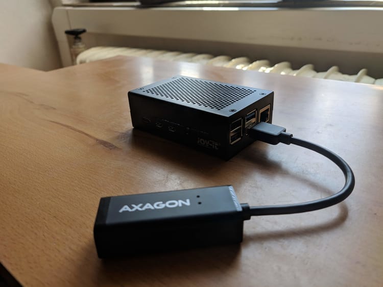
Raspberry Pi is a very affordable little device, which you can use for various projects. It has outstanding Linux support, and its official Linux distribution, Raspberry Pi OS, runs on all supported Raspberry Pis.
If you develop a project on Raspberry Pi 3B+ and then insert your microSD card into a Raspberry Pi Zero, your code may still just work. One of the great benefits is a 40-pin GPIO header.
Along with libraries like gpiozero, even beginners can use GPIO without hassle. But Raspberry Pi is not a microcontroller, and Raspberry Pi OS is not a real-time OS. If you need to perform time-critical tasks, you may get into trouble, as we did.
In this blog post, we'll dive into the development of a stopwatch for firefighter competitions and discuss some of the issues we were facing. You can find the full source code here.
Firefighter Stopwatch
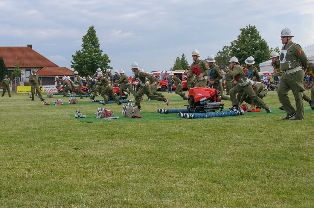
We called our project "Firefighter Stopwatch." If you have no clue what's going on in a firefighter competition, take a look at this video.
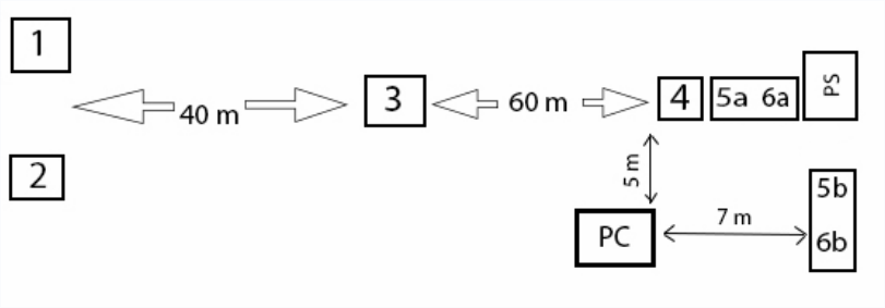
There are four checkpoints. When firefighters reach checkpoint 4, the stopwatch starts measuring time. After they reach checkpoint 3, the application measures split time. Points 2 and 1 work the same, except that the checkpoint which the firefighters reach last will stop the clock.
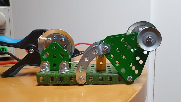
We don't only measure time. Each time a checkpoint is reached, we measure water flow and pressure inside a hose, as well as the engine's RPM. We also added support for manual data measurement triggered by a dedicated button, and we log the results into a CSV file.
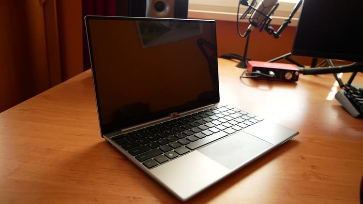
We present all the results during the competition on an external monitor. For this project, we decided to go with Raspberry Pi. It's affordable, has a small form factor, and has enough performance to handle measuring and displaying data at the same time.
User Interface
We decided to implement this project in Python 3. This language is widely used and is excellent for fast prototyping. As a GUI library, we chose Tkinter, built on top of the lightweight Tk library. The final UI looks like this:
If you're not familiar with this library, you create the whole UI via code. This library provides various widgets, like Frame, Label, or Button. You can change the appearance of the widgets with custom styles and position them inside a window using the geometry manager. The most commonly used manager is called a grid. You need to place each widget into a table with columns and rows. The largest widget placed inside a column or row determines the dimensions of that column or row.
And here's our first problem. If you look at the UI, you can see that when you run our app, there is no data. Widgets take less space, and the window is smaller. As soon as you start measuring values, the window size changes rapidly. Take a look at the screenshot below.
You can see the window collapsing on the first run. Once you start measuring data, it is resized. Here it's not that annoying, but we modeled an unrealistic scenario where all measured values are the same. As a result, the geometry manager resizes our window only once.
But let's imagine a real-world scenario where captured data differs and falls into different ranges. When you stop the engine, you'll measure zero RPM, but this value can climb up to 100,000 RPM very quickly, and then drop below 10,000 RPM. In such a case, the geometry manager will resize the window several times. It's not very pleasant, and we had to deal with it.
Our first approach was to reserve some extra space by putting empty whitespace characters as placeholder text inside the widget. It didn't solve our problem, but it was a move in the right direction. Ultimately, we decided that we needed to specify the allowed range of values for each measured component. For instance, we enabled RPM ranging from 0 to 99,999. In a real-world scenario, RPM won't reach the maximum value, but now we can ask the widget to reserve enough space to fit all input data under all circumstances.
label = ttk.Label(content_frame, style='Customized.Main.TLabel',
                  padding=(30, 10), width=10, anchor='center')
label.grid(column=1, row=9)
label.grid_remove()
You can specify widget size using width. Please refer to the documentation for more information. You can center the text inside the widget with the anchor attribute, assuming the input is smaller than the maximum value. Now the UI is more pleasant.
Another thing we needed to deal with was changing the widget's visibility. During manual measurement, the UI shows the time of capturing the data and an M symbol next to it. Then, after two seconds, this information is hidden. The geometry manager comes to the rescue!
label = ttk.Label(content_frame, style='Customized.Main.TLabel',
                  padding=(30, 10), width=10, anchor='center')

# Position and display widget on the screen
label.grid(column=1, row=9)

# Make widget invisible
label.grid_remove()

# And make it visible again
label.grid()
Note that when we want to make the widget visible again, we don't need to provide a grid position anymore. The grid manager remembers the last position of the widget and shows it instantly.
Architecture
Our application consists of several classes, as you can see in the diagram below.
classDiagram
direction TB

class TkWindow {
  mainloop()
}

class MainApp {
  postOnUiThread()
  close()
}

class PressureTransducer {
  get_current_pressure()
  get_sliding_avg_pressure()
}

class RpmMeter {
  get_current_rpm()
}

class FlowMeter {
  get_current_flow()
}

class StopWatch {
  get_current_time()
}

class Button
class BusIO_I2C["busio.i2c"]

TkWindow ..> MainApp : uses
MainApp --> PressureTransducer
MainApp --> RpmMeter
MainApp --> FlowMeter
MainApp --> StopWatch

PressureTransducer ..> BusIO_I2C : uses

RpmMeter --> Button
FlowMeter --> Button
StopWatch --> Button : 1..*
Stopwatch serves to control the clock based on user input and to trigger measurements. The FlowMeter continuously measures water flow. PressureTransducer measures pressure from two connected sensors, and the RpmMeter measures the engine's RPM. All these classes post messages into the MainApp component, which handles an event loop and performs all processing on its UI thread. If you try to update a UI widget from a background thread, your application will most likely crash. Android works very similarly.
Handling GPIO inputs with gpiozero
Gpiozero is a small library that abstracts operations over GPIO. It was originally built on top of RPi.GPIO, but over time support for other libraries was added. It allows, among other things, using GPIO remotely from your PC as if it had GPIO on board.
To process GPIO inputs, we used the Button component. This component creates a background thread to process GPIO input. It continuously polls for input changes and calls your function when such a change occurs. We use the Button component not just for handling button presses, but for any signal input. Remember, the button is just an abstraction, and the library configures the input pin as needed.
The following code shows how to attach an input pin to the button and register your function as a callback:
_STOPWATCH_TRIGGER_PIN = 26

start_button = Button(self._STOPWATCH_TRIGGER_PIN, pull_up=True, bounce_time=0.1)
start_button.when_pressed = lambda: self._start_watch()

def _start_watch(self):
    # Code to run
    pass
You need to connect your callback to the when_pressed property. The Button component expects a function with a specific signature. Ideally, you should reference a function without input parameters, or you can pass a function that assumes one input parameter. When called, it will receive a proper reference to the Button object.
We use buttons inside classes, and their functions have self as an input parameter. To make this work, we use an anonymous lambda function that calls the code we need.
With this approach, we could build our components from the ground up. The stopwatch component directly handles input signals for controlling the clock; RpmMeter gets triggered each time it receives a pulse from the engine sensor, and so on.
Remote GPIO
Gpiozero supports remote GPIO. We won't go into details here. Let us assure you that it is very convenient, and working with your Python code on your PC instead of your Raspberry Pi is a feature you don't want to lose once you try it. In some sense, it resembles working with Arduino boards on a PC. Although Raspberry Pi is powerful enough for many tasks, developing your code on a much more powerful PC saves time.
However, when you try to run scripts written for Raspberry Pi on a PC, some libraries don't expect such an environment and will raise an exception. Therefore, we handled problematic code with a try...except block and turned such features off.
One example is I²C communication using CircuitPython's Busio library. Because this library won't run on a PC, we won't get data from the pressure sensor over I²C, but everything else works just fine.
This approach allowed us to debug and resolve most of the issues on a PC and spend only the necessary time developing directly on a Raspberry Pi.
Adafruit CircuitPython
CircuitPython is Adafruit's flavor of MicroPython. It's a version of Python for microcontrollers. Previously, when you bought a sensor from Adafruit, they provided libraries and guides for the full-featured Python version as well as for MicroPython. This approach is deprecated, as it is worse for maintaining the code. What Adafruit recommends instead is using its compatibility layer, called Blinka. Through this library, you can use code written for CircuitPython, which is the approach we chose as well.
Event Loop
When an event occurs, i.e., the clock trigger is pressed, a component—in this case, StopWatch—processes the event and notifies the MainApp by calling MainApp#post_on_ui_thread(event). MainApp runs an event loop that processes all events and refreshes the UI when needed. Just a reminder: UI updates need to be handled solely by the UI thread. Internally, we use the synchronized Queue class.
# Queue for UI thread to update components
self._thread_queue = queue.Queue()
You can put data into the queue like this:
def post_on_ui_thread(self, value):
    self._thread_queue.put(value)
And you can read the data during UI refresh like this:
def _update_ui(self):
    try:
        event = self._thread_queue.get(False)

        # Events without data
        if type(event) == str:
            if event == StopWatch.STOPWATCH_RESET:
                # Reset clock
                pass
            if event == StopWatch.MANUAL_MEASURE_ENDED:
                # Do some work
                pass

        # Events with data as dicts (key = value)
        elif type(event) == dict:
            checkpoint = None

            for eventKey, eventValue in event.items():
                if eventKey == StopWatch.SPLIT_TIME_MEASURED:
                    # Display split time on a screen
                    pass

    except queue.Empty:
        pass

    # This line ensures that the update function gets called
    # periodically to pick up events from the queue. SCREEN_REFRESH_MS allows
    # us to precisely control how often this function gets called.
    self._parent.after(self._SCREEN_REFRESH_MS, self._update_ui)
Processing data from sensors
Sensors attached to Raspberry Pi don't provide values that can be used directly as-is. Instead, we need to compute what we need. As samples arrive, we store them inside a circular buffer. For that purpose, we use the deque class from the collections module.
For instance, if you want to store the last ten samples as they arrive, initialize deque as follows:
self._samples = deque(maxlen=10)
When a new sample arrives, it is appended to the end of the buffer, effectively dropping the oldest sample.
self._samples.append(time.time())
You work with this buffer like a standard list that has ten elements. Neat!
Computing RPM from pulses
Our sensor is located right inside the engine. It generates a pulse each time an induction coil throws a spark. Rapid pulses are received on the GPIO pin. The faster these pulses are, the higher the RPM. We capture the time (in milliseconds) when each sample arrives. From there, we compute the time delta between samples and subsequently calculate frequency. Finally, we derive RPM from the rate.
freq = 1 / ((self._samples[-1] - self._samples[0]) / self._MAX_QUEUE_LENGTH) / self._k_multiplier
rpm = int(freq * 60)
At the moment, we compute the time delta between ten samples. Perfect sampling precision on Raspberry Pi is not guaranteed, and this approach helps mitigate the problem a little bit.
Computing water flow from pulses
This case is somewhat similar to the previous one in that we also get pulses on input. To compute flow in liters per second, we just need a different equation.
freq = 1 / ((self._samples[-1] - self._samples[0]) / self._MAX_QUEUE_LENGTH)
lpm = int(self._k * (freq + self._q))
Computing pressure
Getting pressure data is trickier. Pressure can rise and decline very rapidly. Therefore, we need to compute its moving average.
The implementation for this module differs. The sensor we use communicates through the I²C bus. We don't use the Button component with its thread. Instead, we create our own background thread that polls the sensor for new samples periodically. This thread runs the following code.
def _update_sliding_avg_pressure_thread(self):
    if self._i2c_initialized:
        self._is_measuring = True
        self._voltage_1_samples.append(self._adc_channels[0].voltage)
        self._voltage_2_samples.append(self._adc_channels[1].voltage)
        self._is_measuring = False
When we later query for pressure, we compute its value as follows:
def get_sliding_avg_pressure(self):
    # Sliding average is computed from _MAX_QUEUE_LENGTH samples
    avg_p1 = sum(self._voltage_1_samples) / self._avg_samples_no
    avg_p2 = sum(self._voltage_2_samples) / self._avg_samples_no
    return tuple(map(self._calculate_pressure_from_input_value, [avg_p1, avg_p2]))
Configuration file
If you look closely, you'll see that in our formulas we use various user-defined constants. These are defined in a configuration file loaded during application initialization. This configuration file gives us the flexibility we need. We've also defined fallback default values as constants inside our code.
Issues
And now the fun part! Some of the less significant problems we've already mentioned. Those were already solved. Now we'll briefly take a look at issues that we mitigated only partially.
RPM fluctuates on a steady pulse stream
When we generate pulses with a specific frequency, the computed RPM should be constant. In reality, this is not the case. During testing, our RPM value fluctuated within a ±100 range, meaning that if the engine runs at 10,000 RPM, you'll see values ranging from 9,950 to 10,050 RPM. We ultimately concluded that for this type of project, such precision is acceptable, although it doesn't mean we're happy with it.
Water flow fluctuates as well
This issue is very similar to the one above, except that water flow fluctuated within a smaller range.
Pressure change isn't reflected instantly
The change in voltage didn't reflect in pressure change immediately. We could probably fine-tune pressure computation further. Changing the size of the circular buffer could be an effective mitigation. For our case, however, it's acceptable.
Logging slows down data capture significantly
In our code, we use the logging module extensively. We've initially set its verbosity to show all messages with DEBUG priority and above. This proved to be a problem when logging occurred in threads performing data sampling. Ultimately, forcing our logger to print only warning and error messages did speed things up.
Solution
When we look at the issues, we can see a pattern. Data sampling accuracy is affected because we don't use hardware designed to work in real time. Also, Raspbian doesn't have a Linux kernel fine-tuned for real-time operation. All threads are governed by the Linux kernel scheduler. You don't have a guarantee that a background thread will run on a dedicated CPU core all the time without interruption. This is the reason why we don't receive data samples captured at precise moments.
Sometimes the Raspberry Pi doesn't capture samples or records their time of arrival with minor skew. When you work with relatively higher frequencies, this does matter. Such small differences cause RPM fluctuation, which is not negligible.
If we started working on a similar project in the future, we would probably consider using a dedicated microcontroller just to collect all samples at the exact time and compute target values during its idle time.
Arduino microcontrollers seem like the right choice. They support interrupts; therefore, we can hook up a routine to process samples with the highest priority. When no sample is being processed, this microcontroller still has plenty of CPU time to perform calculations. It doesn't run any operating system, after all.
When the Arduino module collects the data, it could periodically send aggregated messages to the Raspberry Pi, which would then display the content on a screen. Even after small hiccups, we still consider Raspberry Pi a perfect tool for handling such simple UIs as ours.
Conclusion
Having GPIO on a Raspberry Pi is a great thing. You can work on many projects without hitting issues like the ones we did. The moral of the story is that if you need maximum precision, handle it on hardware designed for that purpose.
Have you ever worked on a project like this? Did you encounter any of the issues mentioned above, and how did you deal with them? Please tell us in the comments below.